The objective of this lab is to introduce the concept of inter-VLAN routing and demonstrate how multiple physical connections can be consolidated into a single connection through trunking.
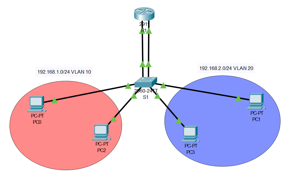
Please familiarize yourself with the topology below before we begin.
At a basic level, the purpose of a VLAN is to split one broadcast domain into multiple. This division accomplishes things such as organization between your network architecture and the reduction of traffic congestion.
This topology has not introduced trunking yet; more on that later. Once the basic setup is complete, which includes enabling the router links, configuring IPs on the interfaces and computers, etc., the configuration for this topology becomes straightforward, primarily involving adjustments on just the switch.
Our first task is deciding what ports should be assigned to what VLAN. Don’t just consider the connections from the router to the switch, keep in mind the interfaces that connect other devices (such as computers). For example, in the above topology, we would have three interfaces assigned to each VLAN. Two interfaces dedicated to the computers and an interface dedicated to the router. Devices connected to interfaces on different VLANs won’t be able to communicate. The VLAN assignment can be achieved using the following Cisco commands:
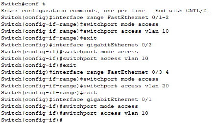
Bang! Just like that, we configured two different VLANs. If the router was removed, these networks would become completely isolated, unable to communicate with each other. Even though we’ve added VLANs to our network, the overall design is still pretty basic. It’s not much different than the usual topology of connecting two separate networks. All we are doing differently is using a single switch and breaking it into two switches, rather than actually using two different switches. Traffic from one network still flows into the router on its own interface… and traffic leaving the router flows out of another interface.
If we continued to use another port for every VLAN, then we’d quickly run out of open spaces. This sparked the rationale behind trunking. Trunking consolidates multiple physical connections into just one. But how does the router differentiate traffic when it’s coming across the same interface? Well, that’s the trick… it won’t be coming across the same interface. We need to logically separate our physical connection by creating sub-interfaces. Before we learn how to configure these connections and sub-interfaces, notice how the new topology only has one connection between R1 and S1.

To begin our configuration, lets start with creating sub-interfaces. The sub-interfaces only take place on the router and don’t need to be configured on the switch.
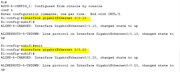
Now that we’ve set up our router sub-interfaces, it’s time to assign our VLANs. The “encapsulation dot1Q <vlan>” command assigns a VLAN to the interface, while “ip address <ip address> <subnet mask>” adds an IP address (this command is just like regular IP configuration on an interface).

The switch configurations stay pretty consistent. Interfaces linked to computers can stay in “access” mode. However, we’ll switch the mode to “trunk” on the interface linked to our router. With this trunk interface, we can designate which VLANs are permitted to pass through it.
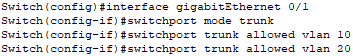
Just like that, we’ve successfully configured a trunked connection between R1 and SW1. Now each network segment can communicate through the use of a trunked connection and router.

Leave a comment