This lab is designed to give you a basic understanding on how static routes function, are configured, and why we use them.
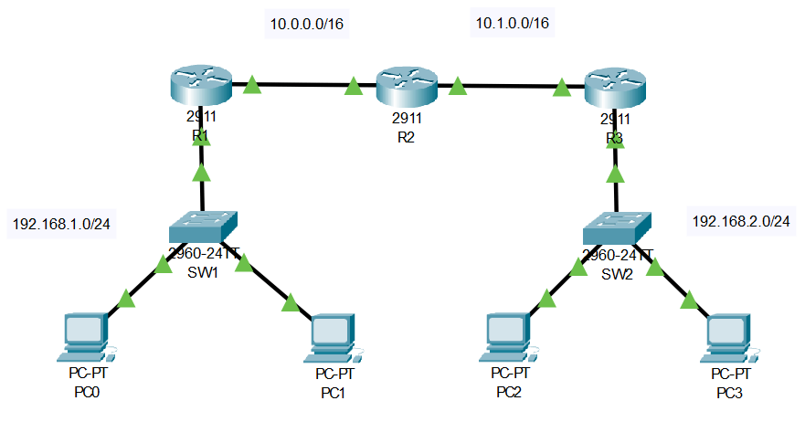
Before we dive in deep, lets back up and take a look at the complete picture. Take a moment to analyze the topology and get a feel for where the networks are located.
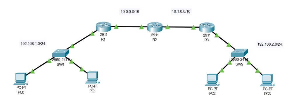
Static routes are the focal point of this lab, but the real goal lies within connecting network 192.168.1.0/24 with 192.168.2.0/24.
You may be asking yourself… cant we connect both networks with just 1 router!? Sure! But that wouldn’t make this lab very fun (we wouldn’t have to configure any static routes; more on that later)? Our first step should be narrowing our focus, we can start by isolating the diagram to just 3 routers.
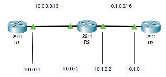
This view provides a much more detailed look at what IPs are assigned to each interfaces. With no routes configured, do you think R1 would be able to ping R3? The answer is no. But why is that? Lets take a look at R1s routing table.
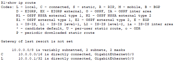
Do you see the issue with this? We cant reach 10.1.0.0/16 because R1 has no clue where its at! What about the other two routing entries? We haven’t configured anything yet, so why are they there? The other two routes are known as “local” and “connected” routes. Those were automatically added when the connection was made on interface Gig0/0. The “connected” route is because we have a direct connection with the other router which also has a 10.0.0.0/16 address. The “local” connection is the IP we configured on this interface.
Now that we’ve diagnosed our issue, lets add a route so we can start talking with R3. In cisco we accomplish this by using the “ip route <ip> <subnet mask> <int>” command. This command requires that we specify what network we’re trying to reach and the interface we need to forward traffic out of to accomplish that. With this scenario, were trying to reach R3. So our complete command would be “ip route 10.1.0.0 255.255.0.0 GigabitEthernet 0/0”. Any traffic destined for 10.1.0.0/16 should be forwarded out of interface GigabitEthernet 0/0. Lets test this connection with a ping.
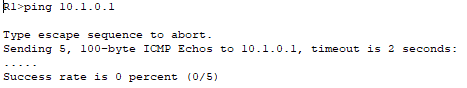
Woah, woah, woah, why did this fail? We set up the connection perfectly. All traffic destined for 10.1.0.0/16 coming from R1 should be forwarded. Well, let’s reverse our logic. If R1 didn’t know how to get to R3… then how is R3 gonna know how to get to R1? If you think we need to add another static route on R3, that’s correct! Here’s how we can accomplish that “ip route 10.0.0.0 255.255.0.0 GigabitEthernet 0/0”. Now let’s try again!
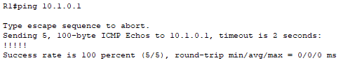
Success! Now every router can talk to each other. The reason we didn’t configure anything on R2 is due to the connected routes mentioned earlier. R2 is directly connected to R1 and R3 so its routes were built automatically.
Now that we have all three routers communicating with each other, let’s scroll back up and remember the goal of this lab. Connecting both 192.x.x.x/24 networks. With the static routes already configured, this is as easy as adding the devices and configuring them with an IP address on their respective 192 networks. These ICMP pings will flow through their network switch, the 3 aforementioned routers, the destination networks switch, the device we are trying to reach, and then back to the device we initiated the ping from. A successful ping from PC0 -> PC2 means eveything was configured correctly.

Leave a comment